Project 02 – Olympus Mju II
by Raymond Yee | October 5, 2016 | Guides, Lens and Camera Modding | 14 comments
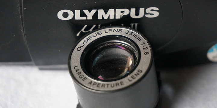
One of the most popular cameras of the 1990s, it is a modern classic – an affordable, stylish, light, small, splash proof camera with a fast and sharp lens coupled with accurate AF. There’s almost no downside to the camera and it is no wonder that Olympus sold almost 4m of this particular model worldwide.
It is one of the cameras I was most excited to modify to fit on my digital cameras. The process itself, however, was far from easy and involved many iterations of the final version of the adapter which I am showcasing here. The challenges were mainly to do with the extraction of the lens unit and then the designing of the adapter which would articulate the shutter/exposure mechanism which is conveniently integrated within the lens assembly unit – which can be extracted (with difficulty) as a single unit. More information can be found in the appropriate project areas.
Lens: 35mm, f/2.8, focusing from 0.35m-infinity. (4 elements in 4 groups)
Optical system construction: Lens is encased in an extended mono block plastic cylinder with 4 lugs which hold the lens block in place on a focusing platform. Also attached to the unit is a combination aperture and shutter mechanism.
Shutter and Aperture: Combined Shutter/Aperture mechanism, single set of 3 blades. Iris is a non linear triangle shape.
Common Failures:
- Battery door failure – very common and replaceable, unless the surrounding area where the door is mounted is also damaged (also common). Tape is crude and effective way to cure this but, inevitably, this is one of the most common source for cheap Mjus on sale on eBay
- Film Transport/micro switch failures: many symptoms for this, ranging from total failure in transport operability, to partial failure with some forms of film transport and flash failure. The latter is caused by the micro switch failure which syncs shutter to flash operations. Both are interlinked and made mainly out of plastic, which has a tendency to fail. Transport mechanism failures can be fixed using gearing from a donor camera but micro switch failures are almost impossible to fix.
Lens Removal:
This is guide on how to remove the lens out of a Olympus Mju II. It is NOT a repair manual. All the cameras I extract lenses from are beyond repair and my method of removing lenses is based on the easiest way of removing the lens at the expense of the donor camera.
The Olympus Mju II is a very densely packed camera, it’s compact form factor means that everything is very tightly packed into the compact body.
 Step 1 – Separate the front and back clamshell
The Olympus Mju II is a splash proof camera and front and rear clamshells are designed to keep moisture out of the camera. The first step is to separate these two by popping open the rear film chamber door and removing the screws highlighted in orange
 Step 2 – It gets ugly, you get creative
See a screw, remove a screw. That is the basic idea. The good news is that most of the parts are plastic so where there is resistance, its relatively easy to break the bits that stand in the way to you getting to lens. There is no way of extracting the lens without sacrificing the camera in entirety, be very clear about this. It’s not a case of being careful, some of the parts in the camera are welded together and can only be forcefully separated, with no chance of reassembly.
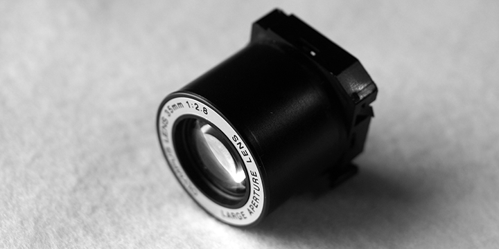
The Prize. The extracted lens unit is approximately 24mm at it’s widest (not including the lens mounting lugs) and 25 mm high.

The rear of the lens. Note the large and bulbous rear element (compared to the front). This throws light at acute angles towards the edges.

Rear, the aperture/shutter wide open. Actuation of the aperture/shutter is via a tab in the bottom right of the lens unit.

Aperture/shutter closed down approximately half way. Note the triangular aperture. The aperture/shutter will close down completely when fully articulated.
Method of conversion:
- Complex 3d printed mount in two parts, secured with a screw
- Lens mounted between base of the mount and secondary enclosure
- Base unit has prongs to articulate shutter/aperture blades
- Mount coupled to Leica M mount close focus helicoid
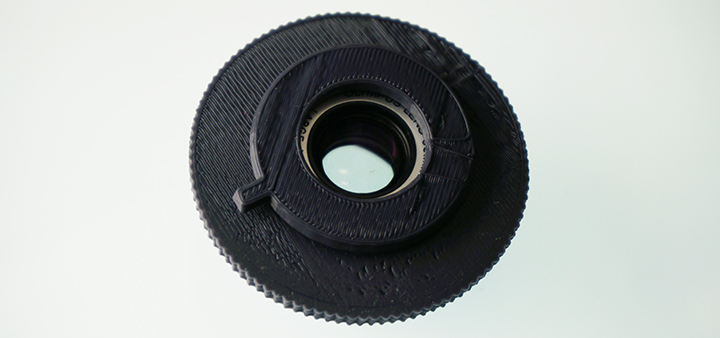

The adapter mount consists of two pieces – a base unit and a lens mount, which also has a handle to articulate the lens unit’s aperture/shutter mechanism

The lens unit mounts onto the lens mount piece by friction fit. It will be farther secured when attached to the base unit which has a lip to prevent the lens and mount units from travelling

The lens and lens mount unit is attached to the base unit. The base unit has a pair of prongs to articulate the shutter/aperture mechanism

The base unit has a slit to allow for the articulation of the shutter/aperture mechanism

The anchor screw attaches to the lens mount unit via a point which is printed in the lens mount unit. Here, I’m showing the mounting point without the outer base unit attached.

The final, assembled adapter, with both units attached. The lever on the bottom left is used to articulate the shutter/aperture mechanism.
Sample Images
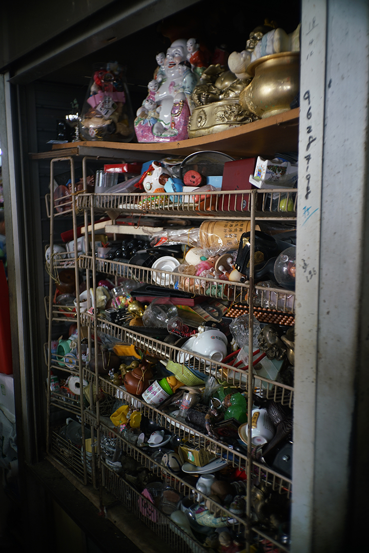

Some initial photos taken with the lens, full resolution versions and more photos taken with the lens can be found in on my Flickr album
Results and Conclusion:
The Mju II is the first real disappointment I’ve had so far (I’m sure that there will be more) in my efforts to convert compact camera lenses to work on digital cameras.
As you can see, the results from the images I have used to summarise the lens performance, the images are tack sharp in the centre but this sharpness rapidly disappears towards the edges. Additionally, closing the aperture/shutter blades does little to increase the depth of field of the image captured or increase edge sharpness.
The main culprit for this is the, bulbous, wide rear element which spreads the image from the lens across the size of a 35mm frame. The flange distance between this element and the film plane is very small – approx 9 millimetres. The last element in the lens group does this by distributing light onto the film plane at very acute angles. Fine if it the final capturing medium is film, not so good if the capturing is being done by a digital sensor with a (relatively) thick piece of glass in front of it. The results are a distinctively smeared image and there’s nothing that can be done about it.
It’s a major disappointment as this is undoubtedly a very sharp and fast lens. Being able to utilise this on digital cameras would have been a major achievement. As it stands, I cannot recommend that you try to convert this lens for any practical purpose. The narrow flange distance and rear lens element characteristics mean that you will never be able to overcome the edge performance characteristics with the current digital sensor technology.
Additionally, the 9mm gap means that the converted lens will not mount on most APS-C sensor cameras as most of them have a blanking plate around the sensor which will prevent mounting of the lens. The lens (with enclosure) diameter is wider than an APS-C sensor so it will only mount on a full frame sensor camera.
Having said that, I learnt a lot converting this lens and look forward to seeing how it can potentially perform on my M mount film cameras, using hyperfocal focusing. Watch this space, as they say.
Flikr Groups:
https://www.flickr.com/groups/659149@N23/
Camera Review links:
http://www.35mmc.com/05/06/2013/yashica-t5-the-path-to-enlightenment-part-1/
- Olympus mju-II / Stylus Epic – Sample Images
- In Sylvain Halgand’s collection – Olympus Mju II
- Olympus mju II and mju II LIMITED in the official Olympus Global History.
- Olympus mju II Quartzdate on Olympus Asia.
- Olympus Stylus Epic review on antiquecameras.net.
- Olympus mju II review by Patrick Hudepohlon on Photo.net
- User opinions of the Stylus Epic on PhotographyReview.com
- Jim Tardio’s equipment report of the mju II/Stylus Epic
- Jim Simon’s Mju-II and what it does
14 Comments
-
 john on 2nd January 2017 at 4:46 pm
-
Raymond Yee on 3rd January 2017 at 1:54 pm
Hi John, Happy New Year! In its current state, the short answer is no. I would need to do some calibration and mark out the different focal distances on the mount so that you could estimate the focal point or use hyperfocus
5Reply5
(google it if you’re unfamiliar) That’s something I was planning to do over the holiday period but I dislocated my shoulder. If you have a 3D printer and the lens, I’d be more than happy to describe to you what needs to be done and let you have a go yourself. Else, you’ll have to wait a bit for me to get around to doing it. Cheers
-
-
Emiliano on 23rd January 2017 at 2:54 pm
This looks very promising! You should try it on a digital Leica, as they have worked around the “microlens vignetting” that you get in these sample images (I think the lens mount has to be 6-bit coded). It might be better to print a an LTM barrel instead of M-mount… See http://www.filmwasters.com/forum/index.php?topic=8535.0
5Reply5-
Raymond Yee on 23rd January 2017 at 3:03 pm
LOL, it’s a small world. I sent Claudio my M mount design and he did the modifications to LTM/M mount adapter. He sent me his version and I’m pretty much using his LTM based mount in all my mount designs, altering it (length of thread) to suit the flange distance of the lens I’m mounting. I was about to try 8-bit coding and have recently gotten access to a colimator which may, with a lot of tinkering, allow me to rangefinder couple lenses but a shoulder injury got in the way. I’ll pick up where I left off as soon as I recover from the operation and physiotherapy.
5Reply5-
Emiliano on 31st January 2017 at 11:57 am
I am very glad to hear that the LTM/M mount can be achieved. I’ll be checking your blog for updates, this is a really nice job. Get well soon!
5Reply5
-
-
-
nano on 30th March 2017 at 1:39 pm
Hi Raymond,
Your site’s been an inspiration and a frequent resource as I work on my own 3d-printed lens conversion adapters. I had a thought recently — spurred by noticing the same mounts used by MS-Optics for all conversions of the same focal length — to help me streamline my process, and wanted to run it by you:
Do all lenses of the same focal length need exactly the same amount of travel to focus? E.g. if I have two 28mm lenses with different flange distances, will they both have the same exact focus travel between 0.7m and 1.5m, 5m & infinity, etc? If so, I could design basic focal length mounts with adjustable flange distances instead of designing new mounts for every new conversion.
Thanks for sharing your work!
-nano
5Reply5-
Raymond Yee on 30th March 2017 at 3:43 pm
Hi Nano, thanks for your kind comments and please do share with me what you are up to yourself. On my part, I’ll share whatever knowledge I have with you. I have not posted much recently due to personal injuries and the fact that I have been spending my time during recuperation working with a camera repair person to learn more about the more technical aspects of photography. Bear in mind that I am not a photography technician and am still learning. I’ll answer your question by email directly to you, tomorrow, as it’s a bit late in the day here. Cheers – Ray
5Reply5
-
-
Michael on 21st August 2017 at 1:58 am
-
Raymond Yee on 21st August 2017 at 5:40 am
Hi Michael,
I’m not releasing the current version of the files as they need to be improved before I am happy to let others have them. Will keep you in mind and let you know when I release them, which will be downloadable from my archives page.Cheers
Ray
5Reply5
-
-
Eric Jang on 22nd December 2017 at 1:06 am
Hello, I have a problem that I wanted to ask.
My Mju II have some problems. For one, back door LCD wont show anything, and secondly after shooting the whole roll of film, it wont rewind the film… Do you know the fix for these issues?
I suspect backdoor need to be changed for LCD but for rewind problem.. I have no idea what could be the problem.
5Reply5-
Raymond Yee on 24th December 2017 at 3:46 pm
Hi Eric,
Merry Xmas, sorry to hear of your problems. I do not have a ready answer for you regarding the LCD and rewind button. There are many reasons why they could fail, the most obvious one being that one of the circuit boards in the camera ha failed. I have come across many LCD failures, usually due to the flexible circuit board which goes around the hinge of the film chamber door being severed, and they are not usually repairable but does not impede shooting beyond not being able to change flash settings, backlight compensation and having to guess how many frames you’ve shot. However, the fact that your auto rewind does not work would have me guessing that one of your logic boards is fried. I might be wrong of course, difficult to say without looking at your camera but, unfortunately, the only suggestion I have is for you to have it inspected by a camera repairman and hope for the best. Cheers.Ray
5Reply5
-
-
William Roper on 19th May 2020 at 8:49 pm
Hi I have a MJU ii but have the following problem, after I take a photo, and try to close the lens cover it hits the lens so I have to slide the cover open again and then close it a second time before the lens retracts.
5Reply5-
Raymond Yee on 20th May 2020 at 3:31 am
Hi William, it’s difficult to tell what the problem with but the 2 things that come to mind are either a weak battery (causing slow retraction of the lens) or a faulty lens cover. There is a electrical contact point on the slider rails which makes contact with another on the cover when you slide the cover, sending a signal to retract the lens. If this is dirty, then the first attempt to retract the lens would “clean” the contact and the second would make it happen. OR… The contacts are spring loaded, can’t remember if it the cover side or the body side, and over time the springiness diminishes or fails so it may be that. The best advice that I can provide, if you are unable to have a repair person look at it or would like to try and fix it yourself, is to replace the battery first and see if it fixes the problem. If it doesn’t help, then remove the slider cover and try to clean the contacts or restore the spring. There are videos on YouTube which show you how, it is a little fiddly and I don’t know how handy a person you are so please proceed at your own risk if you decide to go down this path. If neither of what I have suggested works, then the problem will most definitely require work by a repair person. The other thing which comes to mind is that the capacitor which powers the motor is not working efficiently (capacitors weaken and fail over time), which will absolutely need replacing to rectify the issue. Good luck!
5Reply5
-
Submit a Comment
Your email address will not be published. Required fields are marked *
Save my name, email, and website in this browser for the next time I comment.