Minolta X-300/370 and X-500/570 Capacitor Replacement Guide /December 23, 2017
Here are some instructions for replacing the primary electrolytic capactior found in several Minolta film SLR bodies. I came across a few examples of this operation in the far corners of the internet but those had small, low-quality photos and I wanted to provide something that's hopefully more detailed and easier to folllow.
This guide applies primarily to the X-500 (or X-570 as it was marketed in the USA) but should also apply to the X-300/X-370 as well. The photos shown here are of the former. The X-700 has, as I understand it, a similarly-positioned capacitor under its base but it also sports an additional capacitor at the top of the camera and the replacement of that isn’t covered here. If your X-700 is giving you trouble then you could do worse than starting here and seeing if it fixes your issue though.
Many electrolytic capacitors contain an electrolyte in liquid form and, with the passage of time, this eventually evaporates, leaving the capacitor with an impaired ability to hold an electrical charge. As the capacitor weakens any sudden load, such as that which occurs during shutter firing, is increasingly taxing the battery directly - this causes the voltage to drop momentarily (known as “sag”) before returning to its previous level. Once the degree of voltage sag becomes too high the camera will shut down as the remaining voltage provided by the battery is no longer sufficient to power the other circuitry. Replacing the capacitor with one of the designed capacity removes the load from the battery and, in many cases, is all that’s required to get the camera working again.
The camera used in this guide was received in a working state but as the original capacitor was still in place I opted to replace it preemptively. To determine if the capacitor is the original or if it has been replaced previously take a look at the voltage listed on the capacitor can - note that you may need to gently lift the capacitor up and out of the camera body by half a centimetre or so in order to see all of the text. The capacitor is mounted on a semi-flexible circuit board so a little bit of movement shouldn’t hurt anything. If the voltage rating is 4V then it is likely to be original as this is less widely available nowadays than the 6.3V parts commonly used for replacement. Other possible signs to look for are differences in the solder joint (colour, shininess, quality) relative to other nearby joints, and whether the capacitor appears to be a tight fit in the depression where it lives, again indicating that it might not be the originally-specified part.
Required Tools
An extensive toolkit isn’t needed for this job. As long as you have a half-decent soldering iron and the skills to wield it then you’ll just need a standard screwdriver to access the circuitry beneath the base plate.
- Small Philips-head screwdriver
- Soldering iron
- Small, long-nosed pliers or tweezers
- Solder (optional if simply re-using existing solder on the joints)
- Solder wick (optional, for cleanup)
Capacitor Selection
The original capacitor from the X-500 and X-300 will be either a 200uF or 220uF, 4 volt, electrolytic cap and most likely of the reputable Nichicon brand. Suitable replacements are easy to get, although capacitors with a 6.3V rating are likely to be much more widely available - you can freely go to a higher voltage rating but be aware that the physical size of the cap often increases as you do so.
I used a Nichicon USR0J221MDD 6.3V, 220uF cap, available at RS Electronics with part number 475-8719. I like RS because, unlike Mouser or Farnell, they don’t have a minimum order quantity, which makes small, one-off orders like this more reasonable. Even small orders often quality for free next-day shipping to boot!
The capacitor I chose is from the SR series and is 6.3mm in diameter and 7mm in length. This provides a good fit with plenty of room to spare. You could get away with a longer cap but I wouldn’t use one with a diameter much above 7mm as it might be a tight fit near the base.
Process
- First, make sure that any film and batteries have been removed from the camera. Or don’t, and embrace the thrill! I like to be certain that I’m not going to cause any issues if I accidentally short out any contacts with the soldering iron or solder wick.
- Remove the four screws holding the base plate to the internal frame. Note that there are two shorter screws and two longer screws - keep these together and take note of their location. Lift the plate up and away, there’s nothing attached to it underneath.
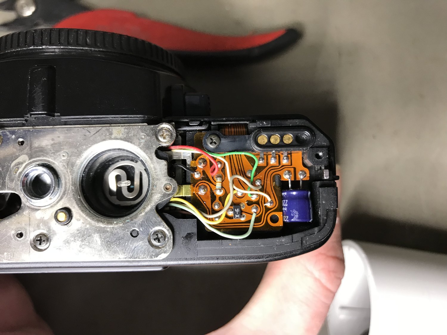
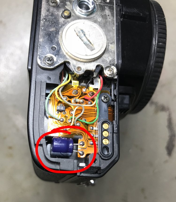
- Now we can see the capacitor nestled away at the right hand edge (with the camera upside-down and the mount facing away from you). The two solder joints at the base of its legs are where we will need to heat to remove it. Unlike on a rigid, through-hole PCB the component legs don’t protrude down through the circuit board - they’re just soldered to pads on top - and this simplifies the process since nothing needs to be moved or removed for access to the reverse side.
- Heat each leg in turn, lifting it gently up and away from the pad with a pair of tweezers as you do so. An alternative, if that's not working so well, is to hold the capacitor can with the tweezers instead and to rotate the whole body. The PCB is semi-flexible so it might also lift a little bit during the process and that's okay.
- Optionally, use some solder wick (braid) and a dab of flux to quickly remove any old solder from the pads and then add a little fresh solder to each pad.
- Trim the legs of your replacement capacitor to an appropriate length. This is easier if you removed the old capacitor without snipping its legs as you have a reference but you can always use a little trial and error, coupled with a Mk.I Eyeball, to find the right length as well. Be aware that by making both legs the same length (required for the cap to be oriented correctly) we’re removing one of the ways by which we can identify which leg is positive and which is negative. The image above shows the correct orientation of the capacitor with the negative side (indicated by the stripe on the can) facing outwards and the positive side facing towards the inside of the camera.
- Hold the replacement capacitor in place using tweezers and solder the first leg using the solder that is already on the pad, plus a small amount of solder loaded on the iron tip, to avoid the need to feed in additional solder from a spool. We only need small amounts here. Repeat for the second leg, for which the cap should sit in place on its own.
That's all there is to it. Once the camera is reassembled with batteries installed take a few test shots without film to see whether the proper shutter operation has been restored.
Hints and Tips
Try to keep the soldering iron temperature relatively low if your iron is adjustable; this reduces the risk of melting or scorching the flexible PCB. I used a temperature of 380C as the tip was very small but the temperature could be a little lower for a larger tip.
Hi Paul. Excellent instructional. I just got an X570 with what seems like a busted capacitor. I put on fresh zinc-air batteries and the led inside the viewfinder would be flashing. Knew about the capacitor issue with these cameras and came upon your post. I'm in the US so your recommendation for the capacitor would end up costing a bit more for me but I found this:
Nichicon 220uf 220ufd 6.3V Volt 105 Degree Hi Temp Radial Electrolytic Capacitor
https://www.ebay.com/itm/Nichicon-220uf-220ufd-6-3V-Volt-105-Degree-Hi-Temp-Radial-Electrolytic-Capacitor/173374802509?epid=2226973415&hash=item285df18a4d:m:mFwI8s0KjoJ9qcQRhjq2d8A
You think the specs would be good enough? It's a bit long at 11mm so I wanted to ask if you think this would work. Thank you!
THANK YOU ever so much for posting this clear tutorial! This was just the ticket in bringing my mom's old Minolta X-570 back to life. Much appreciated.
Gel-Flux is needed if re-using the old solder and/or if one-handed soldering.
Thank you very much for taking the time to write this down. I’ll try to do it myself right now.
I hope everything went well. Nice gallery of product photos on your site over there!